Nokia Lumia 620 as an ECG Recorder.
Includes wrist - wrist - leg cardiac conections
Disclaimer
Do not connect the Nokia to its 230v mains charger or via any high voltage equipment while making ecg measurements. Electrical faults can and do occur with any electrical equipment from time to time and as such it is the responsibility of the user to take all safety precautions needed. If you do not understand what precautions are needed you should not be attempting to use this ecg in any way since wrist to wrist connections are measuring voltages across the electrical path across the heart.
Specs.
A 9 volt battery provides power to the differential instrumentation amplifiers. RC filters provide noise reduction. An adjustable gain output circuit outputs the ecg signal ready for input to the Nokia phone complete with Led pulse indicator. The ecg-Nokia interface is designed for stable operation via a 4 pin 3.5mm jack plug.
Description.
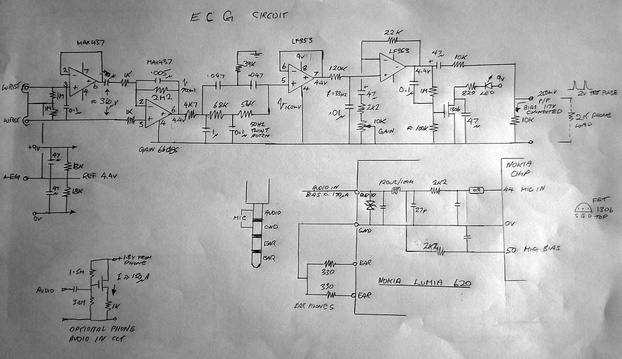
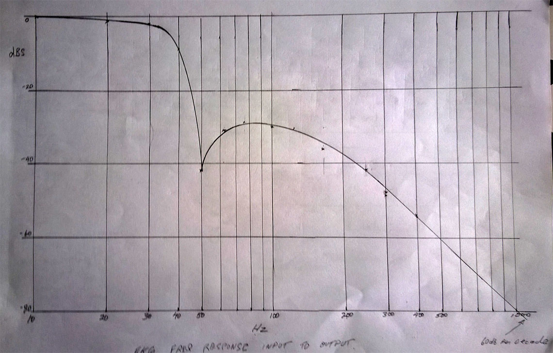
This circuit uses two Max437 instrumentation op amps which were to hand when the project was started. Most any high impedance amplifiers can be used for these stages but the offset voltages must be basically zero in order to enable the high gain needed for the differential amplifier. The gain is set about 66 dbs to boost the microvolt signals obtained from the wrist - wrist connections. Since the cardiac signal can be expected to be around 1 pulse per second and includes significant electrical noise from local mains wiring complete with other electrical disturbances filtering the signals is imperitive. The leg connection anchors the body and its noise pick up to the virtual ground reference point which reduces most of the noise at the inputs. To this end the pre amp roll off begins at about 15 Hz and is followed by an output pole at 33 hz. A 'twin T' filter tuned to reject 50 hz passes the signal into the first section of a LF353 twin op amp connected as a voltage follower driver for the final adjustable gain output amplifier. The final amplifier is adjusted to provide a signal level suitable to drive the Nokia input circuit and the output Led driver.
Nokia Lumia 620 Interface.
The Nokia input circuit is quite important and deserves a special mention. Normally this input socket expects a Fet based microphone plus earphones of some sort. The earphones are obviously not required so these connections are unused but the microphone circuit expects to deliver a 2 volt bias output to a Fet based microphone. In addition, when recording applications are initiated, a series of test pulses are sent from the Nokia to the microphone to determine if the microphone to be used for recording is external or internal to the Nokia. If incorrect microphone loading is present, the Nokia may determine that there is no external microphone and therefore switch to the phone internal microphone or cause unstable operation when recording from an external signal. The Nokia test signal expects a current load of about 150 microamps which means the ecg signal output load should not be lower than about 10k ohms and needs to be ac coupled so that the recording signal can drive with reference to the Nokia output voltage level. Plug the jack into the Nokia before initiating the recording program. I used 'Pocket Recorder' which has an 'audio visualizer' on which audio signals can be just seen when the pulse is in sync with the recorder.
The attached circuit and diagrams show the details of this project.
Examine the results.
The recorded file can be viewed using any suitable audio editor by transferring the file to a PC or lap top in the usual manner. An alternative 'Lexis Audio Editor' which is Win 8.1 Nokia based editor was found capable of displaying the ecg recording without the need to transfer the file from the Nokia. This has all the usual editing functions including normalising to adjust the amplitude to fill the screen.
Construction.
Any suitable box, preferably screened to prevent noise pick up will do. Provide a battery on/off switch and input the wrist and leg connections directly to avoid connection problems at the input stage. Wrist connections were fashioned from 15mm copper tube with a single longitudinal cut and then squashed flat in a vice then prised open. Screened connection wires were soldered (center only) to the copper contacts with the screens connected to the virtual earth reference point. The contacts were then clamped to 10mm wide elasticated band which was stitched to form a cuff to slip over the wrist. The leg band was similar except a press stud closed around the lower leg to keep the contact in place. AloVera dish washing soap, which has enough conductivity, was used as an interface for the contacts to reduce the interface resistance. This can be applied via syringe when the bands are in position.The ecg output was connected to a floating 4 pin 3.5 mm jack plug so that the Nokia can be disconnected when not in use. Be careful to feed the signal to the Nokia 4 contact jack plug with audio contact closest to the cable.
Circuit Diagram:
Response of Filters including Twin T Notch:
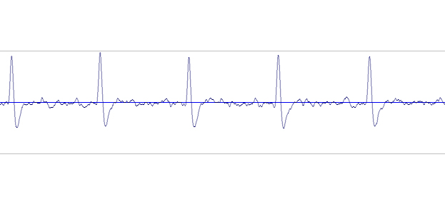
Recorded Nokia Signal:
NB. Due to lack of Nokia bandwidth at frequencies below 50 hz, this wave shows reduced low frequency content.
Lap Top Recording:
A band width test down to 1 Hz verified the response was as below.
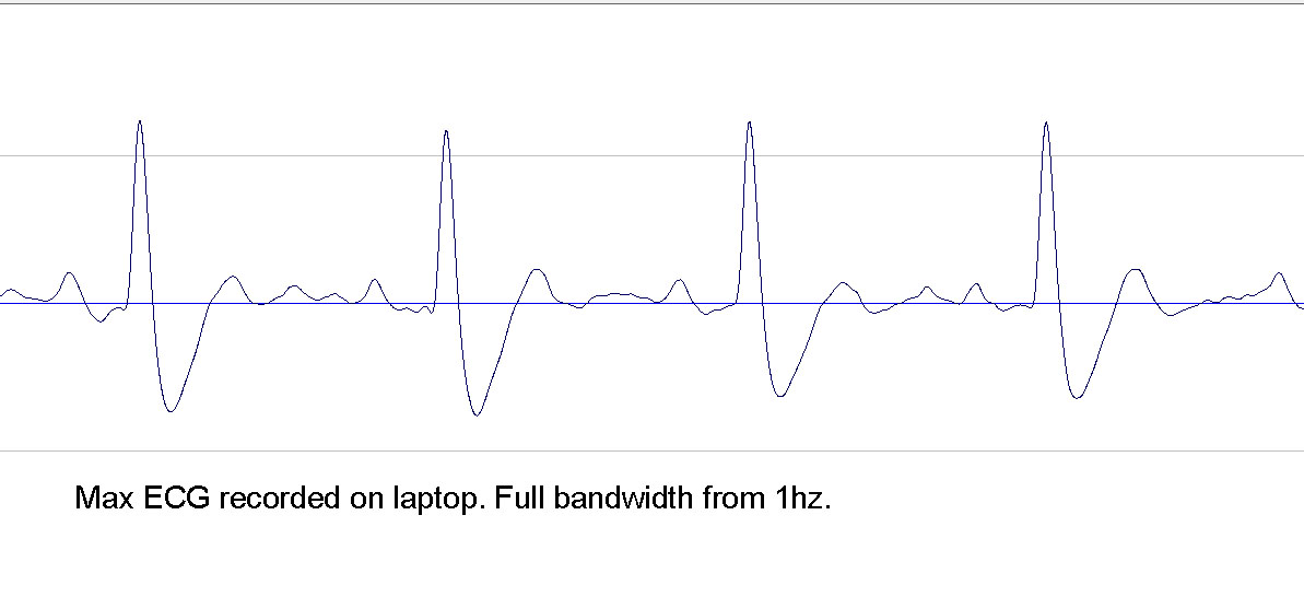
To record the wave without low frequency signal losses on a Nokia Smart Phone, it may be necessary to use the signal to modulate a 10Khz carrier before recording and then de modulate for display purposes.